


Is the Probe that’s Placed on the Injured Site the Positive End of the Electricity? Meaning, are Electrons Being Pushed Out of the Probe Head Into the Body?
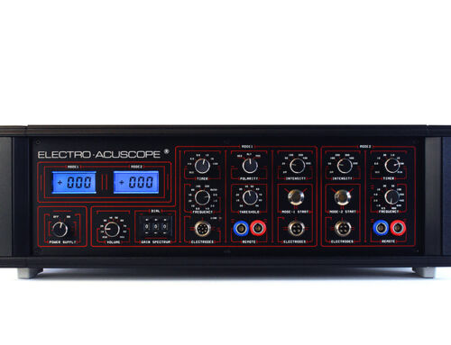
Answer: The Trigger Probe Tip (or any electrode plugged into the red ring jack) both delivers the corrective influence into the tissue and also picks up biofeedback.
We now call it the “Active” electrode. The other probe (or any electrode plugged into the blue ring jack) is called the “Reference” electrode.
During feedback mode, the degree of impedance in the tissue between the two points of contact is being measured and revealed to us. The resistance to a current force of 3-4 µA (microamps) is shown as numbers on the digital display of Mode-1.
At this time the Active Probe is in Negative Polarity (pulling information FROM the body into the instrument for analysis); and the Reference Electrode is in Positive Polarity (pushing the current toward the Active). The current is moving only in one direction when we are seeing a readout; this is known as a Direct Current (DC) in a closed circuit.
During treatment mode, once you push the Start Button, the Polarity of the tips switches every two seconds. Negative (-) Polarity pulls and Positive (+) Polarity pushes. This causes the current to move back and forth from tissue into instrument (reading) and from instrument out to tissue (treating) and vice versa, again and again. The directionality of the current continually reverses until treatment stops. This is called Alternating Current (AC). There is a 000 readout on the digital display during treatment.
Because the instrument is programmed to send and receive in this way, it is important to keep the Active electrode closer to the brain when the Reference is lower down the body. The Acuscope is programmed to send and receive exactly as the brain and body are programmed to operate; the brain sends downward; and receives feedback back up from below.
It is very important to understand this fundamental concept when providing Acuscope treatments.
If the Timer is set, for example, at 12 seconds, then after 12 seconds of treatment, the Acuscope reverts back to readout mode, revealing the improvement in conductivity in terms of higher numbers on the digital display.
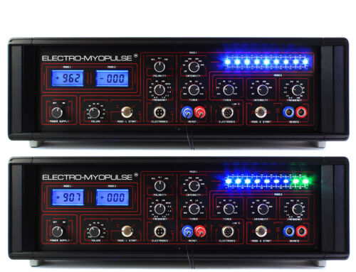
The Myopulse does not reveal tissue impedance values until treatment is initiated. This is shown as constantly fluctuating numbers in the digital display window during treatment. It is also indicated by the LED lights cascading up and down the scale. The lights and numbers (and corresponding sounds) are actually depicting the peak pulse points in a sinusoidal pulse train.
When considering this aspect of the Myopulse, it is important to keep in mind that this instrument “expects” to deliver a corrective influence into the connective tissue when the current is moving downward from muscle origin towards insertion; it is programmed to pick up informative biofeedback when the current is moving upward in the opposite direction.
Thus, as with the Acuscope, it is essential that Myopulse electrodes be placed accordingly, regardless of which choice of electrodes are being applied. For example, if a placement electrode is attached at the neck, near the origin of the trapezius muscle, it should be plugged into the Active (Red ring) outlet; the other placement electrode is placed further down the trapezius, under the scapulae or anywhere towards the insertion below, and it is plugged into the Reference (Blue ring) outlet.
It’s a good question to ask. Feel free to call if this is not perfectly clear to you. It is a very important factor to understand.
Jan